

ข้อมูลทางเทคนิค
In measurement with the highly-accurate transducer connected through a long extension cable, cable conductor resistance and ambient temperature change cause measurement errors. The remote-sensing function removes these factors causing errors and stabilizes the excitation voltage.
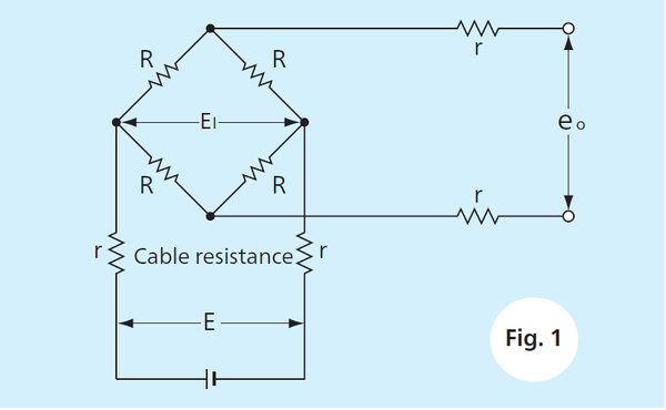
If, for example, the 0.5 mm2 conductor cabtyre cable is extended by 100 m, the conductor resistance is approximately 4.0 Ω. If the cable resistance “r” in Fig. 1 is 4.0 Ω, the reciprocating resistance on the input circuit is 8.0 Ω.Suppose input and output resistances are 350 Ω, then the voltage at both ends of the bridge is:
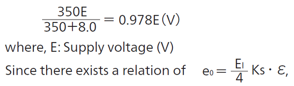
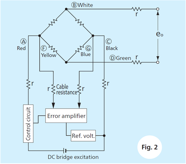
the sensitivity of the transducer lowers by approximately 2.2%. Furthermore, if ambient temperature changes by 10°C during measurement, voltages at both ends of a transducer fluctuates by about 0.1% and accuracy of transducer even 0.02%RO is diminished. As shown inFig.2, the remote-sensing method has one additional pair of cable for detecting errors resulting in 6-conductors.
In the remote-sensing method, although excitation voltage is lowered by cable resistances "r", this lowered voltage is leaded by detecting wires to an error amplifier and then be compared to standard voltage. This different voltage is amplified by an error voltage amplifier with high-amplification and high-impedance. Then, this voltage output drives a control circuit. As a result, input voltage to bridge is kept constantly without effects of cable resistances, leading to accurate and stable measurements. In this case of remote-sensing method, connections and conductor colors are shown in Fig.2.
In the remote-sensing method, although excitation voltage is lowered by cable resistances "r", this lowered voltage is leaded by detecting wires to an error amplifier and then be compared to standard voltage. This different voltage is amplified by an error voltage amplifier with high-amplification and high-impedance. Then, this voltage output drives a control circuit. As a result, input voltage to bridge is kept constantly without effects of cable resistances, leading to accurate and stable measurements. In this case of remote-sensing method, connections and conductor colors are shown in Fig.2.